Select Page

Hydraulic Electro-Pump Units with Fixed Flow

Hydraulic H.F. Units

Hydraulic Electro-Pump Units with Fixed Flow units are mainly designed for large pleasure boats, fishing and work crafts. Owing to a very strong construction, large oil tanks, high reliability of the pumps and distributors and to the easily accessible external mounting of elements connected with flexible tubes, these devices are the leaders on the market in the field of hydraulic electro-pump units.

Hydraulic H.F. Units
Hydraulic H.F. Units Dimensions Drawing

Tank volumeFlowrate
Weight
ABCC
2200190 HF 1-2.510 litres2,5 l/mn750460220125
2.65 US gall35 kg29 (17/32)18 (7/64)8 (5/8)4 (59/64)
2200148 HF 1-310 litres3 l/mn750460220125
2.65 US gall35 kg29 (17/32)18 (7/64)8 (5/8)4 (59/64)
2200149 HF 1-410 litres4 l/mn750460220125
2.65 US gall35 kg29 (17/32)18 (7/64)8 (5/8)4 (59/64)
2200150 HF 1-625 litres6 l/mn750560270225
6.62 US gall45 kg29 (17/32)22 (3/64)10 (5/8)8 (7/8)
2200151 HF 1.9-910 litres9 l/mn750560270225
6.62 US gall57 kg29 (17/32)22 (3/64)10 (5/8)8 (7/8)
2200195 HF 1.9-1110 litres11 l/mn770560270225
6.62 US gall57 kg30 (5/16)22 (3/64)10 (5/8)8 (7/8)
2200955 HF 3-1550 litres15 l/mn810785270450
13.2 US gall61 kg31 (57/64)30 (29/32)10 (5/8)17 (3/8)
2200562 HF 3-1810 litres18 l/mn810785270450
13.2 US gall62 kg31 (57/64)30 (29/32)10 (5/8)17 (3/8)
60 bars maximum pressure – Note : Standard 24 VDC. Other voltages upon request

Hydraulic Power Packs with Adjustable Flow (non reversible)

Power Packs with Electrovalves

Hydraulic Power Packs with Adjustable Flow (non reversible) in 12 or 24 V for pleasure, fishing and work boats. They are fitted with an electro-distributor and an oil reservoir. Flow adjustment is done through a screw which allows accurate regulation of the time required for lock to lock displacement.

12 VOLTS24 VOLTS
Power Pack EV2>strong/>22004092200980
Power Pack EV322008442200981
Caution : The pressure limiter has been factory adjusted (30 bars max. pressure). Please do not modify.

EV2EV3
Maximum cylinder capacity (cc)432650
Power pack flow rate (l/mn)0.2 à 20.3 à 3
Oil reservoir capacity1 L1 L
Recommended protection 12/24 V25 A / 16 A30 A / 16 A

Power Packs EV2 EV3 Dimensions Diagram

EV2, EV3
A803 (5/32)
B983 (7/8)
C30511 1/64
D2424 (15/16)
E391 (35/64)
F42 (3/4)
G2208 11/16

Power Packs EV2 EV3

Reversible Power Packs with Adjustable Flow

Reversible Power Packs for Double Rod Cylinders

Hydraulic reversible Power Packs with adjustable flow in 12 or 24 V for pleasure, fishing and work boats. They are reversible by changing the polarity on the motor terminals. Flow adjustment is done through a screw which allows accurate regulation of the time required for lock to lock displacement. These power packs are fitted with lock valves.

12 VOLTS24 VOLTS
Power-Pack RV122008432200944
Power-Pack RV222004102200945
Power-Pack RV322004032200946

Reversible Power Packs for Single Rod Cylinders

Hydraulic reversible Power Packs with adjustable flow in 12 or 24 V for pleasure, fishing and work boats fitted with a single rod cylinder (unbalanced cylinder on outboard or stern-drive motors). They are reversible by changing the polarity on the motor terminals. Flow adjustment is done through a screw which allows accurate regulation of the time required for lock to lock displacement. These power packs are fitted with lock valves.

12 VOLTS24 VOLTS
Power-Pack RV2-Z22032402203261

Power-Packs RV1 RV2 RV2-Z RV3

RV1RV2 / RV2-ZRV3
Maximum cylinder capacity (cc)216432650
Power pack flow rate (l/mn)0.1 à 10.2 à 20.3 à 3
Recommended protection 12/24 V16 A / 6 A25 A / 16 A30 A / 16 A
30 bars maxi pressure – other pressures, contact us.

Power-Packs RV1 RV2 RV2-Z RV3 Dimensions Drawing

RV1, RV2 / RV2-Z, RV3
A803 (5/32)
B983 (7/8)
C30011 (13/16)
D2424 (15/16)
E391 (35/64)
F702 (3/4)
G44

Selection of the System

For boats equipped with a hydraulic steering, it will be necessary to determine:
– The volume of the steering cylinder (take the biggest volume in case of a single rod cylinder)
– Available voltage on board (12 VDC, 24 VDC, etc.)

For planing or semi-planing hulls, the power pack will be selected in function of its flow rate so that the steering cylinder will run its complete stroke within 10 to 12 seconds.

For displacement hulls, the power pack flow rate must enable the steering cylinder to run its complete stroke within 15 to 17 seconds.
Examples:

  • Speed boat, planing hull with a 239 cc cylinder – Available voltage 12 VDC60 seconds (1 minute)
    —————————-
    12 seconds (required time) x 0.239 litre (239 cc) = 1.195 litre / minute
    The flow rate of the required power pack will be 1.19 litre / minute, therefore we will select a reversible power pack with adjustable flow rate type RV2 (12 V)
  • Fishing or work boat, displacement hull with a 2,307 cc cylinder – Available voltage 24 VDC60 seconds (1 minute)
    —————————-
    15 seconds (required time) x 2.307 litre (2307 cc) = 9.228 litre / minute
    The flow rate of the required power pack will be around 9 litres / minute, therefore we will select a power pack type HF 1.5 – 9 (24 V)


For boats equipped with a mechanical steering (wire ropes, cables, rack and pinion), it will be necessary to determine:

– The rudder(s) torque
– The available voltage on board (12 VDC, 24 VDC, etc.)

Torque Calculation:
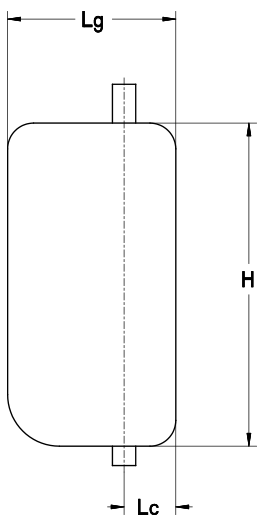
For boats fitted with a rudder with speed not exceeding 25 knots, the torque (C) of the rudder or rudders will be calculated according to the formula and correction coefficients below:

C = S x [ (0.4 Lg) – Lc ] x V² x K

C = Torque in kpm
S = Total surface of rudder (H x Lg) in sq. m
H = Height of rudder in m
Lg = Width of rudder in m
Lc = Compensation width in m
V = Maximum speed of the boat in knots
K = Coefficient according to total angle of rudder

Port to starboard70°K = 15.89
Port to starboard80°K = 17.80
Port to starboard90°K = 19.52

Torque Diagram

Corrections in function of the type of boat:
For sailing-boatsC x 0.5
For boats fitted with several rudders (catamarans, trimarans, monohulls)multiply the calculated torque result by the number of rudders fitted on the boat
Examples:
H = 1.2 mSpeed under sail = 12 knots
Lg = 0.7 mSpeed with motor = 8 knots
Lc = 0.18S = 1.2 x 0.7 = 0.84 m2
Torque under sail = (0.84 x [(0.4 x 0.7) – 0.18] x 122 x 15.89) x 0.5 = 96.11 m.kg
Torque with motor = 0.84 x [(0.4 x 0,7) – 0.18] x 82 x 15.89 = 85.42 m.kg

Selection of the linear drive:
Torque not exceeding 50 kpmLinear drive type 32ST16 NEWAVE
Torque not exceeding 100 kpmLinear drive type 40ST16 NEWAVE
Torque not exceeding 200 kpmLinear drive type 50ST20 NEWAVE
Torque not exceeding 390 kpmLinear drive type 63ST28 DEBP NEWAVE

In the above example, the calculated torque is 96.11 kpm. Therefore the correct selection will be a linear drive type 40ST16 NEWAVE.

Note : for sailing boats with a modern hull and balanced rudder, the selection can be made in function of the boat length as below:

LengthLinear drive type
Length not exceeding 33 feet32ST16 NEWAVE*
Length not exceeding 44 feet40ST16 NEWAVE*
Length not exceeding 60 feet50ST20 NEWAVE*
Length not exceeding 80 feet63ST28 DEBP NEWAVE*

*Data given as an indication only

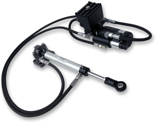
Power Packs and Linear Drives for Autopilots

LS power packs and linear drives for autopilots are perfectly adapted to the requirements of various applications, such as pleasure boating, coastal or deep sea navigation, workboats, professional or recreational fishing, sailing and power boat competition.

They are easy to install, state of the art machine finished and made to withstand the demanding marine environment.

You can easily select the best suited system for your boat within a wide range of equipment.

Our systems carry a 2 year warranty and are fully compatible with all major brands of autopilot electronics available on the market today.

2200843 Linear Drive
2203065 Linear Drive Assembly

Accessories for Work Boats

Fill and Bleed Power Pack “LS SPEEDY PURGE”

2203593 Speedy Purge
LS SPEEDY PURGE is a tool designed to fill and purge air from LS Hydraulic Steering Systems fitted on 5 to 15 metre boats.
LS SPEEDY PURGE connects directly to the 12 volt boat battery with crocodile clips and to the cylinder and pump with 2 x 4 metre clear spiral hoses.
Easily transportable, its 4 litre oil contents gives sufficient autonomy to bring 2 to 3 steering systems into service without filling up.
Fill and purge is done neatly by one technician alone in less than 10 minutes, thus ensuring that SPEEDY PURGE is paid off with the very first steering systems. LS Speedy Purge is the ideal tool for shipyards with small series of boats or for installation or maintenance work at marinas.
2203836   
LS Speedy purge – 12V – with 4 m extension hoses
1206948
Set of 2 x 4 m extension hoses
2203593 LS Speedy purge

Electrical By-pass

2200376 Electrical By-pass NO 06 12 VDC 3/8 BSPP
2201479 Electrical By-pass NO 06 24 VDC 3/8 BSPP
2200566 Electrical By-pass NO 12 12 VDC 1/2 BSPP
2201438 Electrical By-pass NO 12 24 VDC 1/2 BSPP
2200376 Electrical By-Pass

Lock Valves on line

2200078-Lock Valve On Line
2200078 Lock Valve On Line Dimensions Drawing
2200078 Lock Valve on line LS 115

for pumps: 30 HB-without LV, 35 HB-without LV, 40 HB-without LV, 50 HB-without LV, 70 CT-without LV, 90 CT-without LV

2200110 Lock Valve On Line LS170
2200110 Lock Valve On Line LS170 Dimensions Drawing
2200110 Lock Valve on line LS 170

for pumps: 105 CT-without LV, 150 without LV, 170 without LV, 200 CT-without LV

Adaptable Cones

2201138 Adaptable Cone + pin Ø 22 – 2°30 angle
  for pumps: 30 HB, 35 HB, 40 HB
Adaptable Cone + pin Ø 22 - 2°30 angle
2200029 Adaptable Cone + pin Ø 24.5 – 8° angle
  for pumps: 30 HB, 35 HB, 40 HB
2200029-Adaptable Cone + pin Ø 24.5 - 8° angle

Dual Pressure Relief Valve

Dual Pressure Relief Valve
Dual Pressure Relief Valve Dimensions Drawing
2203369 Dual Pressure Relief Valve

By-pass Valves

2200683 By-pass valve–inflexible tube 6 x 8
2200045 By-pass valve–inflexible tube 8 x 10
2200097 By-pass valve–inflexible tube 10 x 12
2202022 By-pass valve–inflexible tube 13 x 15
2200015 By-pass valve–inflexible tube 15 x 18
2200683 By-Pass Valve Inflexible Tube

Bulkhead Strain Relief

2201753 Bulkhead Strain Relief
  Suitable for all LS flexible tubes and all other flexible tubes with an outer diameter of 8 to 12 mm.  
Bulkhead Strain Relief

Pump 200 CT without Lock Valve

2200106 Pump 200 CT

2200135 Pump 200 CT without Lock Valve
Flow rate200 cc/t12.2 cu.in
Minimum size of tubing15×18 mm.59x.70″
Weight17 kg37.5 lbs
Volume2000 cc122 cu.in
Maximum Wheel diameter∅1000 mm39 3/8″
Dimensions Drawing

Accessories for Pump 200 CT without Lock Valve
2200107Set of straight fittings for pump 1/2 BSPP Ø 18 mm
2200110Lock valve LS 170
2200111Set of straight fittings for lock valve 1/2 BSPP Ø 18 mm
2200115Set of tees for Ø 18 mm inflexible tube
2200179Wooden wheel Ø 1000 mm
∅ 15-21 fittings available on request

Pump 150 CT without Lock Valve

2200106 Pump 150 CT

2200130 Pump 150 CT without Lock Valve
Flow rate150 cc/t 9.15 cu.in
Minimum size of tubing15×18 mm.59x.70″
Weight16.4 kg36.2 lbs
Volume2000 cc122 cu.in
Maximum Wheel diameter∅1000 mm39 3/8″
Dimensions Drawing

Accessories for Pump 150 CT without Lock Valve
2200107Set of straight fittings for pump 1/2 BSPP Ø 18 mm
2200110Lock valve LS 170
2200111Set of straight fittings for lock valve 1/2 BSPP Ø 18 mm
2200115Set of tees for Ø 18 mm inflexible tube
2200178Wooden wheel Ø 800 mm
∅ 15-21 fittings available on request

Pump 105 CT without Lock Valve

2200106 Pump 105 CT

2200106 Pump 105 CT without Lock Valve
Flow rate105 cc/t6.41 cu.in
Minimum size of tubing15×18 mm.59x.70″
Weight16.4 kg36.2 lbs
Volume2000 cc122 cu.in
Maximum Wheel diameter∅1000 mm39 3/8″
Dimensions Drawing

Accessories for Pump 105 CT without Lock Valve
2200107Set of straight fittings for pump 1/2 BSPP Ø 18 mm
2200110Lock valve LS 170
2200111Set of straight fittings for lock valve 1/2 BSPP Ø 18 mm
2200115Set of tees for Ø 18 mm inflexible tube
2200177Wooden wheel Ø 700 mm
∅ 15-21 fittings available on request