Select Page

Video guides for installation and maintenance of LS products

Logo Lecomble and Schmitt

We have created this section to help you with the installation and the maintenance of Lecomble & Schmitt products. You will also find all these videos on our YouTube channel: https://www.youtube.com/user/lsfrance.

Please do not hesitate to send us your comments or suggestions in order to improve and develop this section while constantly striving to fully satisfy you.

Installation of LS Cylinders for Outboards

Installation of LS Cylinders for Outboards

Maintenance of LS Outboard Helm Pumps

Maintenance of LS Outboard Helm Pumps

Maintenance of LS Outboard Helm Pumps

Maintenance of outboard helm pump type LS 20 HB

Maintenance of outboard helm pumps type LS 26/40/50 HB

Maintenance of outboard helm pumps type LS 30/35 HB

Maintenance of outboard helm pumps type LS 29/35 CT HB

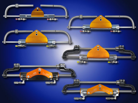
Installation of LS cylinders for Outboard

Installation of LS cylinder VHM EX 80 HP

Installation of LS cylinder VHM EX 125 HP

Installation of LS cylinder VHM EX 175 HP

Installation of LS cylinder VHM EX 225 HP

Installation of LS cylinder VHM EX 350 HP

Installation of LS cylinder VHM EX 3500 HP

Filling and bleeding a hydraulic steering system

Accessories for Power Assisted Hydraulic Steering Systems

2203593 Speedy Purge
LS SPEEDY PURGE is a tool designed to fill and purge air from LS Hydraulic Steering Systems fitted on 5 to 15 metre boats.
LS SPEEDY PURGE connects directly to the 12 volt boat battery with crocodile clips and to the cylinder and pump with 2 x 4 metre clear spiral hoses.
Easily transportable, its 4 litre oil contents gives sufficient autonomy to bring 2 to 3 steering systems into service without filling up.
Fill and purge is done neatly by one technician alone in less than 10 minutes, thus ensuring that SPEEDY PURGE is paid off with the very first steering systems. LS Speedy Purge is the ideal tool for shipyards with small series of boats or for installation or maintenance work at marinas.
2203836   
LS Speedy purge – 12V – with 4 m extension hoses
1206948
Set of 2 x 4 m extension hoses
2203593 LS Speedy purge

Electrical By-pass

2200376 Electrical By-pass NO 06 12 VDC 3/8 BSPP
2201479 Electrical By-pass NO 06 24 VDC 3/8 BSPP
2200566 Electrical By-pass NO 12 12 VDC 1/2 BSPP
2201438 Electrical By-pass NO 12 24 VDC 1/2 BSPP
2200376 Electrical By-Pass

Lock Valves on line

2200078-Lock Valve On Line
2200078 Lock Valve On Line Dimensions Drawing
2200078 Lock Valve on line LS 115

for pumps: 30 HB-without LV, 35 HB-without LV, 40 HB-without LV, 50 HB-without LV, 70 CT-without LV, 90 CT-without LV

2200110 Lock Valve On Line LS170
2200110 Lock Valve On Line LS170 Dimensions Drawing
2200110 Lock Valve on line LS 170

for pumps: 105 CT-without LV, 150 without LV, 170 without LV, 200 CT-without LV

Adaptable Cones

2201138 Adaptable Cone + pin Ø 22 – 2°30 angle
  for pumps: 30 HB, 35 HB, 40 HB
Adaptable Cone + pin Ø 22 - 2°30 angle
2200029 Adaptable Cone + pin Ø 24.5 – 8° angle
  for pumps: 30 HB, 35 HB, 40 HB
2200029-Adaptable Cone + pin Ø 24.5 - 8° angle

Dual Pressure Relief Valve

Dual Pressure Relief Valve
Dual Pressure Relief Valve Dimensions Drawing
2203369 Dual Pressure Relief Valve

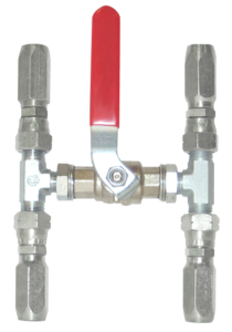
By-pass Valves – Flexible Tubes

2200803 By-pass valve–flexible tube TS 6
2202496 By-pass valve–flexible tube TS 8
2200803 By-Pass Valve Flexible Tube
2200027 By-pass valve–flexible tube Ø 8 mm
2200067 By-pass valve–flexible tube Ø 10 mm
2200027 By Pass Valve Flexible Tube
2200683 By-pass valve–inflexible tube 6 x 8
2200045 By-pass valve–inflexible tube 8 x 10
2200097 By-pass valve–inflexible tube 10 x 12
2202022 By-pass valve–inflexible tube 13 x 15
2200015 By-pass valve–inflexible tube 15 x 18
2200683 By-Pass Valve Inflexible Tube

Torque Calculation for Power Assisted Hydraulic Steering Systems

For boats fitted with a rudder, the torque of the rudder or rudders is calculated according to the following formula and corrections.

It must be known that the torque necessary  to manoeuver a boat depends on:

  • The speed of the water flowing on the surface of the rudder at a certain angle
  • The rudder size
  • The total sweep of the rudder (and part of the boat), if the rudder shaft is not perpendicular
  • The compensating surface of the rudder (balanced rudder)

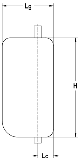
    C = S x [ (0.4 Lg) – Lc ] x V² x K

C = Torque in kgm
S = Total surface of rudder (H x Lg) in sq. m
H = Height of rudder in m
Lg = Width of rudder in m
Lc = Compensation width in m
V = Maximum speed of the boat in knots
K = Coefficient in function of total rudder angle

Port to starboard70°K = 15.89
Port to starboard80°K = 17.80
Port to starboard90°K = 19.52

Torque Diagram

Corrections in function of the type of boat:
For a boat with a steering nozzleC x 2.0
For twin engine power boats with 1 rudderC x 0.5
For boats fitted with several rudders (catamarans, monohulls)Multiply the calculated torque result by the number of rudders fitted on the boat.

Power Assisted Hydraulic Steering Systems

Specifically designed for luxury vessels getting regular and intensive use, LS range of Power Assisted Steering Systems is designed in total compliance with the strictest norms applying to marine equipment.

The recommended solutions for 185 kpm to 2.000 kpm rudder torque are suitable to equip 15 to 40 metre vessels.

Absolute security comes first: steering is still possible even in case of electrical failure.

Features such as smoothness, accuracy and reduced number of wheel turns give LS power assisted steering systems unequalled comfort.

The ease of use of the catalogue enables the shipyards engineering and design departments to define straightaway the correct system in function of the rudder torque, the power supply available on board and the number of steering stations.

Hydraulic Piping from 334 to 3832 kgm

The hydraulic piping represents all the hydraulic flexible tubes linking together the hydraulic components (equipped tank, proportional distributor, by-pass valve, cylinder…). Its definition depends on the number and type of steering system components and on the distances between these components. It also depends on the configuration of the hydraulic diagram (single or double cylinder, elements supplied on the equipped tank or separately).

Each hydraulic hose is fitted with pre-swaged fittings and union fittings on both ends.

Electro-Hydraulic Steering System with Single Cylinder
REEquipped Tank
GMPower Pack
DPSingle Proportional Distributor
BPBy-Pass Valve
VCLCylinder / Linear Sensor

1. Separate power pack and single proportional distributor

Separate power pack and single proportional distributor

1′. Power pack and single proportional distributor mounted on the equipped tank

Power pack and single proportional distributor mounted on the equipped tank
Electro-Hydraulic Steering System with Double Cylinder
REEquipped Tank
GMPower Pack
DPDouble Proportional Distributor 1 and 2
BPBy-Pass Valves 1 and 2
VCLCylinders / Linear Sensors 1 and 2

Example of Hydraulic Piping Setup

Specifications of the steering system configuration:

Electro-hydraulic steering system with double cylinder and separate elements.

In function of the chosen locations for the installation of the elements on the boat, the distances numbered 1 à 11 in the above diagram 2 must be determined.

2. Separate power pack and double proportional distributor

Separate power pack and double proportional distributor

2′. Power pack and double proportional distributor mounted on the equipped tank

Power pack and double proportional distributor mounted on the equipped tank

Electrical Harness from 334 to 3832 kgm

Electrical Harness DEH

The electrical harness consists of all electrical wires connecting the transmitters and receivers to the programmable logic controller. Its definition depends on the number and type of steering system components and on the distances between these components and the programmable logic controller.

Each wire is fitted on both ends with paired pre-swaged connector halves.

Example Electrical Harness Setup

Specifications of the steering system:
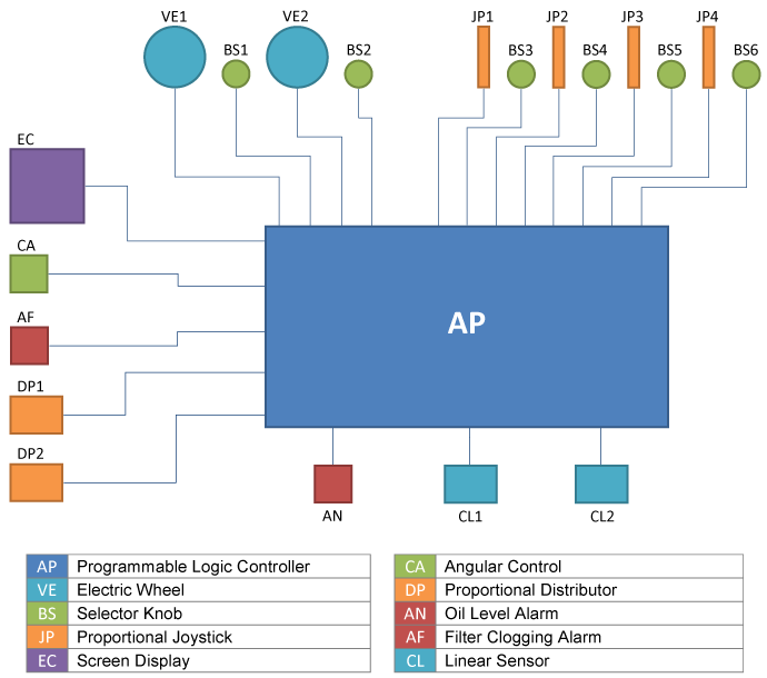
Twin steering station + 1 joystick + 3 selector knobs + 1 screen display + 1 programmable logic controller + 2 cylinders/linear sensors + 1 power pack + 1 equipped tank + 1 double proportional distributor (double cylinder).

Define the individual wire lengths on the above diagram:
VE1/AP ; BS1/AP ; V2/AP ; BS2/AP
JP1/AP ; BS3/AP
EC/AP
DP1/AP ; DP2/AP
AN/AP ; AF/AP
CL1/AP ; CL2/AP

Selection of Steering System from 334 to 3832 kgm

Steering System with Single Cylinder

Single Steering StationDouble Steering Station
2203400*Electric Wheel (2.5 turns)1N/A
2203287*540° Electric Wheel12
2203288Proportional Joystick (FFU)1 to 41 to 4
2203296Selector Knob1 to 52 to 6
2203403*Angular Control1 or more1 or more
2203295Screen Display11
2203961Programmable Logic Controller11
Analog transmitters. Maximum three transmitters of all types per system.
Example of a Steering System Setup
Specifications of the steering system: 900 kgm rudder torque – Double steering station + 1 Joystick – Voltage available: single-phase 230V / 50 Hz
Parts to Select:
2 540° Electric wheels2203287
1 Proportional joystick (FFU)2203288
3 Selector knobs2203296
1 Screen display2203295
1 Programmable logic controller2203961
1 Cylinder + sensor2203442
1 Equipped Tank2203426
1 Single-phase hydraulic power pack2203418
1 Single proportional distributor2203432
1 Tiller arm2203303
1 Electrical harness / 1 Hydraulic pipingLengths to be determined
Torque in kgm 334435588790100015521916
Cylinder + Sensor2203438220343922034402203441220344222034442203445
Hydraulic Power Pack – 3-phase2203412220341222034122203413220341322034142203415
Equipped Tank2203425220342522034252203426220342622034262203427
Single Proportional Distributor2203431220343122034322203432220343222034322203433
Hydraulic Power Pack – 1-phase2203417220341722034172203418220341822034192203419
Equipped Tank2203425220342522034252203426220342622034262203426
Single Proportional Distributor2203431220343122034312203432220343222034322203432
Hydraulic Power Pack 24 Vcc2203409220340922034102203410220341122034112203411
Equipped Tank2203425220342522034252203425220342622034262203426
Single Proportional Distributor2203431220343122034322203432220343222034322203432
Tiller Arm2203300220330122033022203302
2203303
220330322033052203305
Electrical Harness / Hydraulic Piping: in function of the steering system setup .

Steering System with Double Cylinder

Single Steering StationDouble Steering Station
2203400*Electric Wheel (2.5 turns)1N/A
2203287*540° Electric Wheel12
2203288Proportional Joystick (FFU)1 à 41 à 4
2203296Selector Knob1 to 52 to 6
2203403*Angular Control1 or more1 or more
2203295Screen Display11
2203961Programmable Logic Controller11
*Analog transmitters. Maximum three transmitters of all types per system.
Example of a Steering System Setup
Specifications of the steering system: 900 kgm rudder torque – Double steering station + 1 Joystick – Voltage available: single-phase 230V / 50 Hz
Parts to Select:
2 540° Electric wheels2203287
1 Proportional joystick (FFU)2203288
3 Selector knobs2203296
1 Screen display2203295
1 Programmable logic controller2203961
2 Cylinders + sensors2203440
1 Equipped Tank2203426
1 Single-phase hydraulic power pack2203418
1 Double proportional distributor2203434
2 Tiller arms2203302
1 Electrical harness / 1 Hydraulic pipingLengths to be determined
Torque in kgm 640870117615802000232831043832
Cylinder + Sensor22034382203439220344022034412203442220344422034442203445
Hydraulic Power Pack – 3-phase22034132203413220341322034152203415220341622034162203416
Equipped Tank22034262203426220342622034272203427220342822034282203428
Double Proportional Distributor22034342203434220343422034352203435220343622034362203436
Hydraulic Power Pack – 1-phase2203418220341822034182203419
Equipped Tank2203426220342622034262203426
Double Proportional Distributor2203434220343422034342203435
Hydraulic Power Pack 24 Vcc22034102203410220341122034112 x 22034112 x 22034112 x 22034112 x 2203411
Equipped Tank22034252203425220342622034262203428220342822034282203428
Double Proportional Distributor22034342203435220343522034352203435220343522034352203435
Tiller Arm2203300220330122033022203302
220330322033042203304
2203305
2203305
Electrical Harness / Hydraulic Piping: in function of the steering system setup .

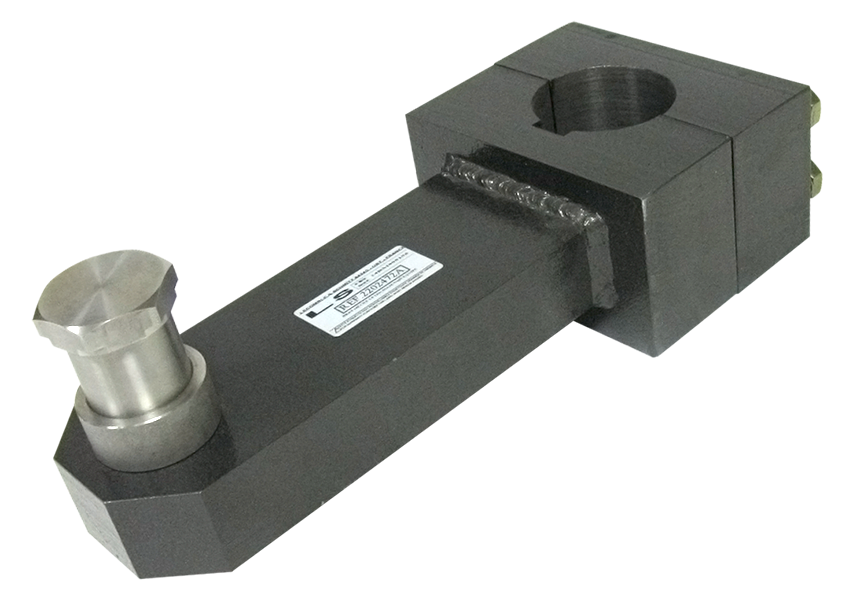
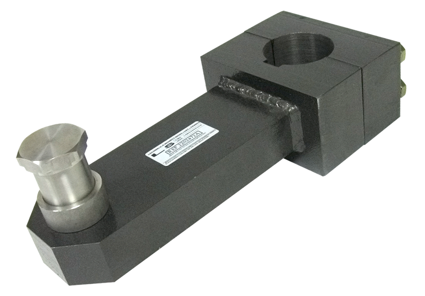
Tiller Arms from 334 to 3832 kgm

2203300 334 kgm Equipped Tiller Arm
Pilot bored Ø 20 mm – Maxi Ø 64 mm

2202472 Equipped Tiller Arm
2202472 Equipped Tiller Arm Dimensions Drawing

2203301 435 kgm Equipped Tiller Arm
Pilot bored Ø 20 mm – Maxi Ø 64 mm

2202472 435 kgm Equipped Tiller Arm
2203301 435 kgm Equipped Tiller Arm Dimensions Diagram

2203302 588 / 790 kgm Equipped Tiller Arm
Pilot bored Ø 20 mm – Maxi Ø 88 mm

2202472 435 kgm Equipped Tiller Arm
2203302 588 - 790 kgm Equipped Tiller Arm Dimensions Drawing

2203303 1000 kgm Equipped Tiller Arm
Pilot bored Ø 20 mm – Maxi Ø 88 mm

2202472 435 kgm Equipped Tiller Arm
2203303 1000 kgm Equipped Tiller Arm Dimensions Drawing

2203304 1164 kgm Equipped Tiller Arm
Pilot bored Ø 20 mm – Maxi Ø 88 mm
For 2328 kgm double cylinder only

2202472 435 kgm Equipped Tiller Arm
2203304 1164 kgm Equipped Tiller Arm Dimensions Drawing

2203305 1552 / 1916 kgm Equipped Tiller Arm
Pilot bored Ø 20 mm – Maxi Ø 100 mm

2202472 435 kgm Equipped Tiller Arm
2203305 1552-1916 kgm Equipped Tiller Arm Dimensions Drawing

Proportional Distributors

2203431 Proportional Distributors

Proportional Distributors
Dimensions Drawing
2203432 10 L Single Proportional Distributors
2203433 25 L Single Proportional Distributors
2203434 40 L Single Proportional Distributors
2203435 10 L Double Proportional Distributors
2203436 25 L Double Proportional Distributors
2203437 40 L Double Proportional Distributors

In accordance with the analogue order received by the programmable logic controller, the proportional hydraulic distributor will provide the flow and hydraulic pressure needed to move the cylinder(s) at the speed and to the positions commanded by the steering wheel, the joystick or any other transmitter.

In the case of a double cylinder installation, its independent modules allow for permanent synchronization of the cylinders. The modules are fitted with relief valves which protect the circuit against excessive pressure rise. They feature manual overrides in the event of a loss of power and are protected by a filter with clogging detection alarm. They can be delivered assembled on the equipped tank or separately for on-line installation between the equipped tank and the cylinders.

Equipped Tanks

Equipped Tanks

Equipped Tanks
Dimensions Drawing

Their volumes are determined by the flow rates generated by the power packs. They are fitted with filling and emptying apertures and oil level sight glass with alarm.

They also feature anchoring studs for the installation of the power packs and proportional distributors.

Depending on the system setup (see “Sélection of Steering System” menu), they can accommodate one or two power packs.

Equipped TanksABCDEF
2203425 Equipped Tank25 L32553035027548011
2203426 Equipped Tank50 L34065044035060011
2203427 Equipped Tank80 L39073050040068011
2203428 Equipped Tank120 L43086555045081511

Power Packs for Electro-Hydraulic Steering

2203410 Power Pack Support Plate

Power Packs
Dimensions Drawing

Power packs are complete assembled units consisting of an electric motor, a hydraulic pump with fittings, a coupling between the pump and the motor and a support plate. Pump and motor capacities vary in function of the volume and the number of cylinders to be driven.
Electric motors can be supplied within certain limits (see “Electro-Hydraulic Steering System with Single Cylinder” and “Electro-Hydraulic Steering System with Double Cylinder”) in 24V direct-current, single-phase or three-phase alternating current. They can be delivered assembled on the equipped tank or separately for on-line installation between the tank and the proportional distributor.

Power PacksABCDEFG
22034090.9 kW – 8 l/mn – 24 Vdc+ support plate220210150435155965
22034101.9 kW – 12 l/mn – 24 Vdc+ support plate2202401604651559105
22034113 kW – 22 l/mn – 24 Vdc+ support plate27024019554515011155
22034121.1 kW – 9 l/mn – 400 VAC 3-PHASE + support plate220250190395155945
22034132.2 kW – 17 l/mn – VAC 3-PHASE + support plate2702652004751501185
22034143 kW – 22 l/mn – VAC 3-PHASE + support plate2702652204801501185
22034154 kW – 32.5 l/mn – VAC 3-PHASE + support plate27028523553015011125
22034167.5 kW – 59 l/mn – 400 VAC 3-PHASE + support plate41033530063019011110
22034171.1 kW – 9 l/mn – 230 VAC 1-PHASE + support plate220270185420155940
2203418 2.2 kW – 17 l/mn – 230 VAC 1-PHASE + support plate2702852004751501185
2203419 3 kW – 22 l/mn – 230 VAC 1-PHASE + support plate2703002204801501180

Receivers: Cylinders / Linear Sensors

Cylinder + Linear Sensor

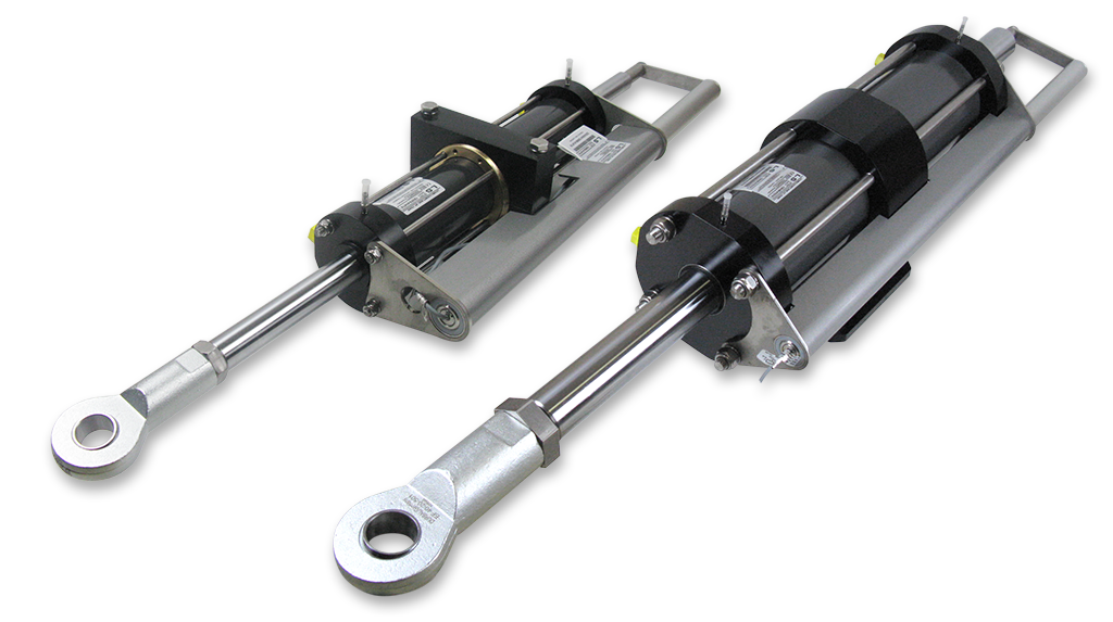
The cylinders provide the power of the steering system.
They are selected by using the methods described in « Sélection of Steering System » menu.

All the cylinders are supplied with their pre-assembled and adjusted linear sensors. The linear sensor is supplied pre-wired with a pre-swaged connector half.

2203438 VHM 60 DT C300 + Linear Sensor
Maximum torque334 kpm2463 ft.lbs
Stroke300 mm11 13/16″
Maximum pressure60 bars870 PSI
Volume664 cc40.5 cu.in
Radius of tiller arm252 mm9 59/64″
Total rudder angle73° (2×36.5°)
Weight18 kg39.5 lbs
Dimension Drawing for 2203438

2203439 VHM 63 DT C345 + Linear Sensor
Maximum torque435 kpm3208 ft.lbs
Stroke345 mm13 19/32″
Maximum pressure60 bars870 PSI
Volume862 cc52.6 cu.in
Radius of tiller arm290 mm11 27/64″
Total rudder angle73° (2×36.5°)
Weight27 kg59.5 lbs
Dimension Drawing for 2203439

2203440 VHM 80 DT + Linear Sensor
Maximum torque588 kpm4336 ft.lbs
Stroke300 mm11 13/16″
Maximum pressure60 bars870 PSI
Volume1167 cc71.2 cu.in
Radius of tiller arm252 mm9 59/64″
Total rudder angle73° (2×36.5°)
Weight32 kg70.5 lbs
Dimension Drawing for 2203440

2203441 VHM 90 DT + Linear Sensor
Maximum torque790 kpm5826 ft.lbs
Stroke300 mm11 13/16″
Maximum pressure60 bars870 PSI
Volume1567 cc95.6 cu.in
Radius of tiller arm252 mm9 59/64″
Total rudder angle73° (2×36.5°)
Weight37 kg81.5 lbs
Dimension Drawing for 2203441

2203442 VHM 90 DT C400 + Linear Sensor
Maximum torque1000 kpm7233 ft.lbs
Stroke400 mm15 3/4″
Maximum pressure60 bars870 PSI
Volume2090 cc128 cu.in
Radius of tiller arm336 mm13 25/32″
Total rudder angle73° (2×36.5°)
Weight47.5 kg100 lbs
Dimension Drawing for 2203442

2203443 VHM 110 DT C300 + Linear Sensor
Maximum torque1164 kpm8565 ft.lbs
Stroke300 mm11 13/16″
Maximum pressure60 bars870 PSI
Volume2307 cc141 cu.in
Radius of tiller arm352 mm 9 59/64″
Total rudder angle73° (2×36.5°)
Weight52 kg115 lbs
Dimension Drawing for 2203443

2203444 VHM 110 DT + Linear Sensor
Maximum torque1552 kpm11446 ft.lbs
Stroke400 mm15 3/4″
Maximum pressure60 bars870 PSI
Volume3076 cc87.7 cu.in
Radius of tiller arm336 mm13 25/32″
Total rudder angle73° (2×36.5°)
Weight55.5 kg122 lbs
Dimension Drawing for 2203444

2203445 VHM 120 DT + Linear Sensor
Maximum torque1916 kpm14131 ft.lbs
Stroke400 mm15 3/4″
Maximum pressure60 bars870 PSI
Volume3798 cc231.8 cu.in
Radius of tiller arm336 mm13 25/32″
Total rudder angle73° (2×36.5°)
Weight62.5 kg138 lbs
Dimension Drawing for 2203445

Programmable Logic Controller

DEH Automate programmable

2203961Programmable Logic Controller
Dimensions Drawing for 2203961

Intended for use on all-terrain machines, our programmable logic controller is of robust design to operate in hostile environments (temperature, moist atmosphere, impacts, vibrations, etc.) It has been programmed to relay orders to the proportional distributor(s) swiftly by using the input data supplied (cylinder linear sensors), the instructions provided (display screen, steering wheels, joystick…) and the data from its built-in computer program.
This type of micro-controller is very responsive. It features physical inputs and outputs which are pre-wired with pre-swaged connector halves.

Screen Display

Electric Wheel

2203295Screen Display
Dimensions Drawing for 2203295

The screen display allows for Human-Machine Interface (HMI) and communication with the logic controller in order to modify the selected settings. Without screen, it is only possible to communicate with the logic controller by the attendance of a qualified programmer.

The screen display offers four configuration modules:

  • HMI (Human-Machine Interface) for the settings
  • Visualization
  • Diagnosis
  • Manual steering control

The HMI module gives direct access to the selection settings for the transmitters and cylinders by activation or deactivation; it makes it possible to act on the parallelism of the cylinders by increments on the boat steering, etc. With a private code (secret code), it also gives access to additional settings such as zero relative bearing, adjustment of the transmitters response angle, maximum rudder angles, lock to lock speed adjustments, decelerations, etc.

The visualization module allows viewing the rudder angles and parallelisms in real-time. It also displays the maintenance schedule of some elements in the system (oil change, filter replacement…) and conveys the alarms (oil level, temperature, filter clogging…) in the form of graphic and/or buzzer.

The diagnosis module allows carrying out a global inspection before starting by testing individual elements in order to identify and isolate the possible failure of a system component and it verifies the supply voltage in real time.

The manual steering control module makes it possible to steer the boat via the display screen keys, thus a substitute for the transmitters.

Transmitters

Electric Wheel

2203400Electric Wheel (2.5 turns)
Dimensions Drawing for 2203400

With this sturdy designed electric wheel, it takes 2.5 turns for the cylinder(s) to travel their full strokes. The electric wheel is affixed with three screws behind a bulkhead and is connected to the electric harness with an identified, pre-swaged connecting pin.
It is equipped with a standard conic shaft end. To be used only on single steering station installations with a steering wheel.

Electric Wheel 2.5 Turns

2203287540° Electric Wheel (1.5 turn with automatic recentering)
Dimensions Drawing for 2203287

With this sturdy designed electric wheel, it takes 540° (1.5 turn) for the cylinder(s) to travel their full strokes. The electric wheel is affixed with three screws behind a bulkhead and is connected to the electric harness with an identified, pre-swaged connecting pin. It is equipped with a standard conic shaft end. Thanks to the automatic recentering function, it can be used for twin steering station installations with two steering wheels.

2203403 Angular Control

2203403Angular Control
Dimensions Drawing for 2203403

This angular control makes it possible to maintain a selected angle to port or starboard by increments of 10 degrees, without having to operate the lever continuously. Easy to install, of sturdy design, its operation is intuitive.

2203288 Proportional Joystick

2203288Proportional Joystick (F.F.U)
Dimensions Drawing for 2203288

Designed to monitor work functions on mobile machinery, this joystick is particularly robust. Featuring centre spring return and digital outputs (CAN), up to four units can be installed at different locations on the boat. Its protection rating corresponds to IP66/67. It also features non-contact detection (Hall Effect) and user-friendly lever ergonomics. Its proportional speed control makes it possible to increase or decrease the cylinder travel speed in function of the lever displacement speed.

2203296 Selector Knob

2203296Selector Knob
Dimensions Drawing for 2203296

When the installation includes several transmitters (steering wheel(s), joystick(s)…), the selector knob is pressed to select the transmitter to be used. It then produces a green light and disables all other transmitters.

Hydraulic Piping

The hydraulic piping represents all the hydraulic flexible tubes linking together the hydraulic components (power pack, by-pass valve, cylinder…). Its definition depends on the number and type of steering system components and on the distances between these components.

It also depends on the configuration of the hydraulic diagram.

Hydraulic Piping Configuration
1Hydraulic Power Pack
2-3Cylinder / Linear Sensor

Hydraulic Piping DEH ECO

Electrical Harness

The electrical harness consists of all electrical wires connecting the transmitters and receivers to the programmable logic controller. Its definition depends on the number and type of steering system components and on the distances between these components and the programmable logic controller.

Each wire is fitted on both ends with paired pre-swaged connector halves.

Electrical Harness Configuration
1Hydraulic Power Pack
2-3Cylinder / Linear Sensor
4-5540° Electric Wheel
6Autopilot Course Computer (not supplied)
7Joystick (optionnal)
8Programming Box

Electrical Cabling DEH ECO

Electro-hydraulic Steering-Selection of the Steering System

Electro-Hydraulic Steering System with Double Cylinder

Depending on the configuration of the steering system – single or double steering station – the boat will be equipped with one or two electric wheels. It can also be equipped with an optional joystick.

Single Steering StationDouble Steering Station
2203287540° Electric Wheel12
2201143Joystick11

Torque in kgm 180296505
Cylinder + Sensor2203810 / 22038112203874 / 22038752203437 / 2203876
Hydraulic Power Pack 12 Vcc220379022038732203873
Hydraulic Power Pack 24 Vcc220387222038042203804
Tiller Arm220330622033072203308
Electrical Harness / Hydraulic Piping: in function of the steering system setup

Example of a Steering System Setup
Specifications of the steering system: 280 kgm rudder torque – Single steering station + 1 joystick – Voltage available: single-phase 24 Vcc
Parts to select:
1 x 540° Electric Wheel2203287
1 x Joystick2201143
1 x Cylinder + Linear Sensor2203874
1 x Cylinder + Reversed Linear Sensor2203875
1 x Hydraulic Power Pack 9 L/mn 24 Vcc2203804
2 x Tiller Arms2203307
1 x Electrical harnessLengths to be determined
1 x Hydraulic pipingLengths to be determined

Programming Box

2203848 Equipped programming box DEH ECO
The programming box allows to adjust the cylinder setup (direction and positions). It connects instead of the autopilot computer during the implementation phase. It will potentially monitor the responsiveness of the autopilot and makes the cylinder bleeding procedure easier.

Functionality:

  • Facilitate the cylinder bleeding procedure.
  • Set the cylinder travel stops (max-min).
  • Determine the cylinder motion direction.
  • Shift the midpoint of each cylinder stroke if required.
  • Memorize the midpoints of the electric wheel(s) displacement.


2203848 Programming Box

Tiller Arms up to 500 kgm

2203306 Pilot bored equipped tiller arm LS 90 kgm
Ø 28 pilot bored – maxi Ø 50>

Pilot bored equipped tiller arm LS 90 kgm
Pilot bored equipped tiller arm LS 90 kgm Dimensions Drawing

2203307 Pilot bored equipped tiller arm LS 148 kgm
Ø 28 pilot bored – maxi Ø 50>

Pilot bored equipped tiller arm LS 90 kgm
Pilot bored equipped tiller arm LS 148 kgm Dimensions Drawing

2203308 Pilot bored equipped tiller arm LS 254 kgm
Ø 28 pilot bored – maxi Ø 50>

Pilot bored equipped tiller arm LS 90 kgm
Pilot bored equipped tiller arm LS 254 kgm Dimensions Drawing

Hydraulic Power Packs DEH ECO

Hydraulic power packs consist of a brushless electric motor coupled to a 6 or 9 litre/minute submersible pump in function of the cylinder volume to be fed. They also feature a hydraulic distribution block fitted with its coils and delivery solenoid valves and its circuit protection components. The oil tank is equipped with an oil level sight glass, a filler cap and an additional opening to allow draining. These power packs support the logic controller to which the electrical harness is connected.

2203790 Hydraulic Power Pack DEH ECO 6 l/mn 12V
2203872 Hydraulic Power Pack DEH ECO 6 l/mn 24V
2203873 Hydraulic Power Pack DEH ECO 9 l/mn 12V
2203874 Hydraulic Power Pack DEH ECO 9 l/mn 24V
Dimension Drawing for 2203790, 2203872, 2203873 and 2203874

Hydraulic Power Pack DEH ECO

Receivers Cylinders Linear Sensors

The cylinders provide the power of the steering system.

They are selected by using the methods described in menu « Selection of the steering system ».

All the cylinders are supplied with their pre-assembled and adjusted linear sensors. The linear sensor is supplied pre-wired with a pre-swaged connector half.

2203810 VHM 40 DTP C234 + Linear Sensor
2203811 VHM 40 DTP C234 + Reversed Linear Sensor
Maximum torque90 kpm633 ft.lbs
Stroke228 mm9″
Maximum pressure50 bars725 PSI
Volume215 cc13.1 cu.in
Radius of tiller arm192 mm7 (9/16″)
Total rudder angle73° (2×36,5°)
Weight5,1 kg11.2 lbs
Dimension Drawing for 2203810 and 2203811

2203874 VHM 50 DTP + Linear Sensor
2203875 VHM 50 DTP + Reversed Linear Sensor
Maximum torque148 kpm1091 ft.lbs
Stroke228 mm9″
Maximum pressure50 bars725 PSI
Volume352 cc21.5 cu.in
Radius of tiller arm192 mm7 (9/16″)
Total rudder angle73° (2×36,5°)
Weight7,5 kg16.5 lbs
Dimension Drawing for 2203874 and 2203875

2203437 VHM 60 DT + Linear Sensor
2203876 VHM 60 DT + Reversed Linear Sensor
Maximum torque254 kpm1873 ft.lbs
Stroke228 mm9″
Maximum pressure60 bars 870PSI
Volume505 cc30.8 cu.in
Radius of tiller arm192 mm7 (9/16″)
Total rudder angle73° (2×36,5°)
Weight18 kg39.7 lbs
Dimension Drawing for 2203437 and 2203876

Joystick

2201143 Joystick

The joystick control operates on an “on-off” basis. The direction of the control lever corresponds to the desired direction the boat is to be steered to. When released, the control lever goes back to its neutral position automatically but the cylinders remain in their last positions. To bring them back to their central positions, the joystick control lever will have to be operated.

2201143Joystick
Dimensions Drawing

540° Electric Wheel (1.5 turn with automatic recentering)

Electric Wheel 2.5 Turns

With this sturdy designed electric wheel, it takes 540° (1.5 turn) for the cylinder(s) to travel their full strokes. The electric wheel is affixed with three screws behind a bulkhead and is connected to the electric harness with an identified, pre-swaged connecting pin. It is equipped with a standard conic shaft end. Thanks to the automatic recentering function, it can be used for twin steering station installations with two steering wheels.

2203287540° Electric Wheel (1.5 turn with automatic recentering)
Dimension Drawing

Torque Calculation

For boats fitted with a rudder with speed not exceeding 25 knots, the torque of the rudder(s) is calculated according to the following formula and correction coefficients.

It should be pointed out that the necessary torque to manoeuver a boat depends on:

  • The speed of the water flowing on the surface of the rudder at a certain angle
  • The rudder dimensions
  • The total sweep of the rudder (and part of the boat), if the rudder stock is not perpendicular
  • The compensating surface of the rudder (balanced rudder)
    Torque Calculation Formula for Speed below 25 Knots

    C = S x [ (0.4 Lg) – Lc ] x V² x K

C = Torque in kpm schema_safran
S = Total surface of rudder (H x Lg) in sq. m
H = Height of rudder in m
Lg = Width of rudder in m
Lc = Compensation width in m
V = Maximum speed of the boat in knots
K = Coefficient according to total angle of rudder

Port to starboard70°K = 15.89
Port to starboard80°K = 17.80
Port to starboard90°K = 19.52

Torque Diagram

Corrections in function of the type of boat:
For sailing-boatsC x 0.5
For a boat with a steering nozzleC x 2.0
For twin engine power boats with 1 rudderC x 0.5
For boats fitted with several rudders (catamarans, trimarans, monohulls)Multiply the calculated torque result by the number of rudders fitted on the boat

Once the torque has been calculated, the appropriate cylinder(s) will be selected and the remaining components of the steering system can be defined.